Address
304 North Cardinal
St. Dorchester Center, MA 02124
Work Hours
Monday to Friday: 7AM - 7PM
Weekend: 10AM - 5PM
Address
304 North Cardinal
St. Dorchester Center, MA 02124
Work Hours
Monday to Friday: 7AM - 7PM
Weekend: 10AM - 5PM

Identify the HMI failure domain, separate panel and terminal scope, and use technical evidence to choose a replacement path and prepare a useful display sourcing RFQ.
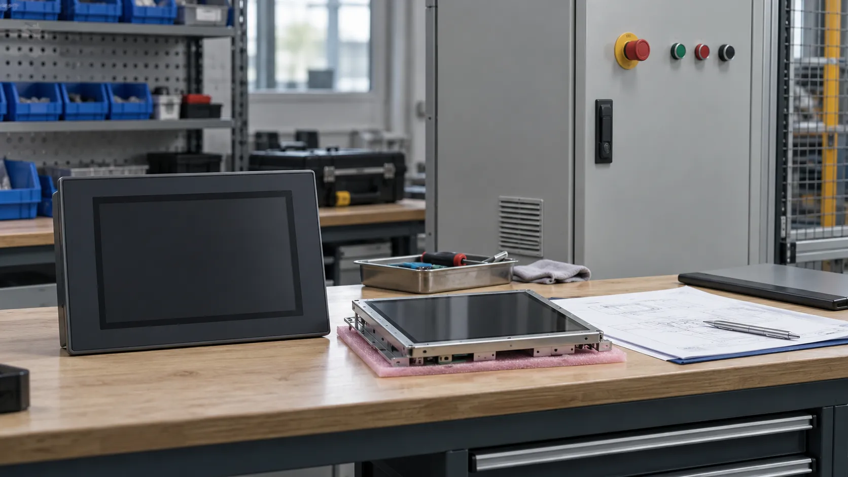
Before an industrial HMI replacement, establish which part of the system has failed and what the proposed purchase actually replaces. A black screen, unresponsive touch or missing controller data can point to different problems. Choose a component, qualified subassembly or complete terminal only when the evidence supports that scope, then validate the restored machine functions before accepting the replacement.
“The screen is dead” is enough to report a breakdown, but it leaves procurement with several possible purchasing objects. The LCD image path, backlight, power supply, display cable or connector, and controller graphics output all belong in the investigation. So do startup, firmware, runtime and operating-system failures: an application that never starts cannot supply the expected operator screen.
Official documentation illustrates why these distinctions matter. Pro-face separates blank-display and touch-response faults in its FP5000 user manual; its display investigation includes host-cable and power conditions. Those checks belong to that product family. They support a broader purchasing principle: a missing image alone does not establish a failed LCD.
A useful failure statement connects an observation to a controlled result. “Black screen after startup” is still a symptom. “The fault followed the display assembly during an OEM-permitted comparison against a documented working baseline” narrows the scope, although it does not isolate every component inside that assembly. Record the test conditions and what remained unchanged; replacing several items at once weakens the conclusion.
A normal image shows that image rendering works under the observed conditions. It does not prove the touch sensor, touch controller, connecting path, driver or calibration is healthy. Conversely, an apparently inactive button may reflect application state or communication with the controller. Pro-face’s touch-response troubleshooting includes both switch behavior and device communication. Local touch recognition and the machine’s response are different evidence.
Rockwell’s PanelView Plus 6 manual, pages 162–168, likewise separates power, startup, display, touch and application anomalies. Its touch investigation distinguishes input-path problems from application problems. A purchase request for an LCD would be premature while that distinction remains open.
Electrical measurements, opening equipment, component substitution and machine command tests must be performed by qualified personnel under the equipment manufacturer’s documentation and the site’s safety procedures. Preserve authorized backups before intervention. This article defines purchasing evidence; it does not supply live electrical test instructions.
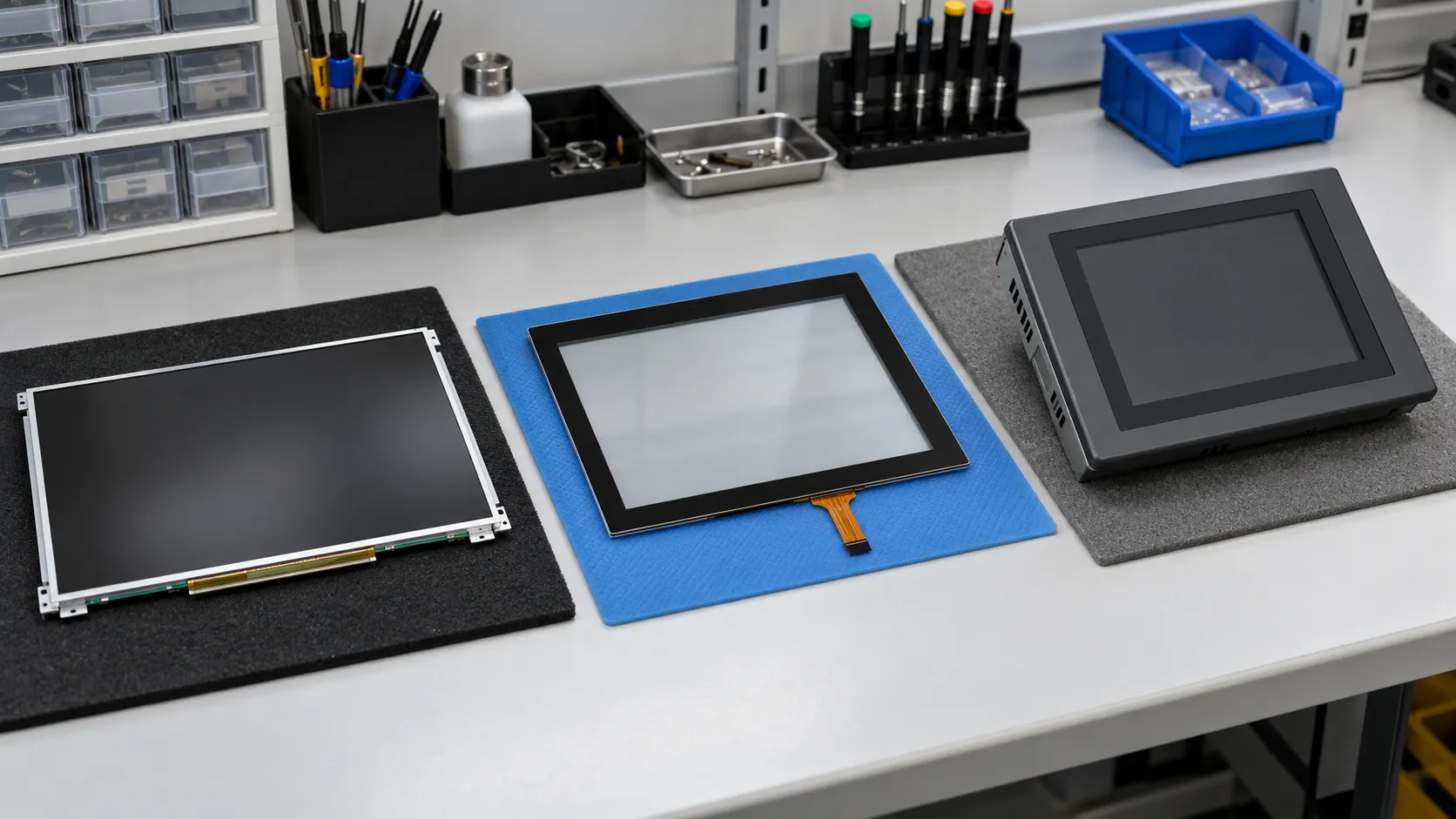
The integration boundary is the dividing line between the purchased item and the hardware, software and enclosure that stay in service. Two offers described as an “HMI screen” can sit on opposite sides of that line. The following working definitions help make quotations comparable; the supplier’s drawing and bill of supply must settle the actual scope.
A panel-level purchase. Define whether it includes a backlight or any supporting electronics. It does not, by that name alone, include touch, the HMI application or a machine-network interface.
An assembled display scope whose included backlight, driver electronics, frame and connections must be stated. “Module” does not establish a complete operator terminal.
Display and touch supplied together. The touch controller, cover lens, bonding, bezel and host connection still need a defined inclusion boundary.
A display with specified control electronics. Establish whether the controller only handles incoming video or also executes application logic; these are different responsibilities.
A display integrated with processing and a software environment. Its firmware, development tools and application interfaces become part of the replacement review.
The operator-device scope, including its specified housing, power and communications. Buying the terminal does not establish that the machine project is included or ready to run.
For a concrete architecture example, ST’s EDT Smart Embedded Display overview describes an integrated HMI module with industrial interfaces, memory and a graphical software framework. That is a different integration task from sourcing a panel. It is an external example, not a Vernon offering or compatibility statement.
A modular design can make a smaller replacement possible, but a physically attachable assembly is not automatically a supported combination. The approval record needs the exact HMI terminal identity, display and logic assembly identities, hardware series or generation, and the manufacturer’s permitted pairing. It must also connect that hardware to the required firmware, runtime and OS, plus the project or application version.
Rockwell documents separately identified display and logic modules in its PanelView Plus 6 manual, pages 15–20. Its FactoryTalk runtime guidance also describes application and terminal-family restrictions and OS dependencies. These are reasons to obtain the relevant OEM evidence for the installed system, not a universal cross-family replacement rule.
A known-good baseline should therefore identify a working hardware/software combination and the conditions under which it worked. It is more useful than an unqualified “tested” label. After a replacement, compare startup, rendering, input and the application functions affected by that change. If the offered LCD revision differs, use the narrower LCD revision-change revalidation guide to develop the component-level review.
An HMI can display its own interface while failing to exchange the required machine data. A communication error therefore does not establish LCD failure. The evidence trail should begin with the existing working path, where available, and identify the controller port and protocol before evaluating the replacement terminal’s settings.
Physical connection or link evidence narrows one layer of uncertainty. It does not establish the correct device address, protocol, application mapping or runtime configuration. Rockwell’s FactoryTalk communication-configuration guidance distinguishes local design configuration from the configuration delivered to the runtime terminal. A working engineering connection is useful evidence, but it should not be recorded as a completed HMI communication test.
For the purchasing record, connect the evidence in this order: existing working path → controller port/protocol → physical/link evidence → HMI configuration → replacement terminal → end-to-end validation. Keep test results attached to their actual endpoints and settings. Otherwise a successful test on one path can be mistaken for proof of another.
Acceptance should cover the functions the machine actually uses: current values, permitted commands, alarms and any required recipes or retained data. Reading a value does not demonstrate that a command reaches the correct destination and produces the intended response. The equipment owner or qualified integrator should define and perform those tests under controlled machine conditions.
The smallest physical part is not always the smallest defensible intervention. Component replacement preserves more of the existing system but needs stronger fault isolation and a serviceable assembly. A complete terminal changes more dependencies and still needs an application and commissioning plan. Use the matrix to choose the next review path, not to approve a part solely from a symptom.
| Possible direction | Evidence supporting this direction | What remains to be validated |
|---|---|---|
| Repair or restore the existing assembly | An OEM-supported repair or configuration recovery addresses the isolated fault; the existing hardware remains suitable. | The fault no longer recurs under relevant conditions; restored settings, data and machine functions meet acceptance criteria. |
| Replace the failed display-related component | Fault isolation identifies the panel, backlight, touch part or cable; the design permits service at that level and the exact component is qualified. | Mechanical, electrical and interface fit; affected image/touch behavior; assembly integrity and operation after reassembly. |
| Replace a qualified subassembly | Evidence localizes the fault to an assembly; its identity, series and pairing with the retained hardware/software are documented. | Startup and runtime behavior with the retained assembly; affected interfaces and machine functions. |
| Replace the complete HMI | Terminal-level replacement is justified; mounting, power, communications and project restoration or conversion have a supported plan. | Installed fit, project execution, controller communication, operator functions and required operational data. |
| Consider system redesign or upgrade | Restoring the present architecture is unsupported or unsuitable, or requirements have changed; an engineering owner and migration scope are defined. | Changed hardware/software interfaces, application migration, operational acceptance, safety review and rollback arrangements. |
If evidence cannot yet distinguish these paths, preserve that uncertainty in the RFQ rather than ordering against a guessed fault. Candidate ≠ Compatible. Once the scope is technically justified, Vernon’s industrial LCD EOL decision guide addresses the separate lifecycle choice between last-time buy, replacement qualification and redesign.
A useful RFQ explains the required outcome and separates established facts from open questions. For example, a buyer who needs an identified display assembly while retaining the logic unit is asking a different sourcing question from a buyer who needs a new terminal and an application migration. The quotation should preserve that distinction.
Include the existing HMI model and full terminal identity; the LCD model and revision where established; and front, rear and label photographs. Add the observed symptom, available diagnostic evidence and the panel/touch/controller boundary. Mechanical drawings, connector orientation and interface constraints help prevent offers that look similar but cannot be integrated.
Where software is involved, describe the firmware, runtime and OS dependencies and whether an authorized project or restore backup is available. State the replacement objective, quantity and project context, then define the validation scope and who owns it. Missing identities or tests should remain explicitly unresolved rather than becoming supplier assumptions.
Attach documents that describe the offered configuration, not merely a related product family. The Preliminary vs Final LCD specifications guide explains the separate question of how document status affects sourcing evidence. That review complements fault isolation; it does not replace it.
It supports only the functions and conditions actually tested. A display test does not establish controller communication, project execution or installed machine behavior. Record its limits and carry the remaining acceptance work into the replacement plan.
Start with the terminal identity, accessible photographs and manufacturer documentation. Mark the internal display identity as unknown. Arrange any further inspection through qualified personnel; do not turn screen size or a photograph into an exact panel identification.
Ask what was tested, with which hardware and software, and under what conditions. The result may help qualify a candidate, but acceptance still needs to cover the buyer’s intended assembly and machine functions.
Vernon is a trading company and China sourcing partner supporting overseas B2B display buyers with requirement clarification, sourcing communication, and supplier coordination.

About the Author
General Manager, Vernon
Saiva is the General Manager of Vernon, a trading company and China sourcing partner supporting overseas B2B display buyers. She supports requirement clarification, supplier coordination, and sourcing communication for LCD display projects.
Share the identified display or assembly requirement, terminal identity, photographs, available evidence, quantity and unresolved integration questions. Vernon can support requirement clarification and sourcing communication; the equipment owner or qualified integrator retains responsibility for diagnosis, software work and machine validation.